


Loop Antenna Design in CST MWS
Objective: To understand, design loop antenna and observe the simulated results.
Antenna-Theory: It is a type of an antenna that is in form of a loop. This antenna consists of one or more number turns of wire forming a DC short circuit which is called a loop antenna. The loop antenna can be of circular, square or
rectangular shape.

Fig. 1.1 Circular loop antenna
Step 1. Parameter Calculation
The center frequency of the required loop antenna is 3 GHz. However the large radius of the loop is 15 mm and small radius of the inner loop is 13 mm. Since the loop is in closed form so we need to create a gap in loop to do the excitation. The parameter for that they are shown here in table of design values.
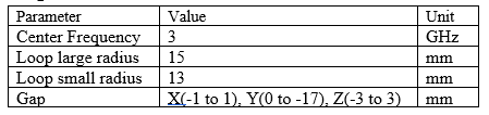
Fig. 1.2 Design values of loop antenna
Step 2. Designing
As you have list of parameters it's time to design the loop antenna in CST software. For that you need to perform following minor steps. All of these highlighted steps are already explained in half wave dipole antenna design tutorial.
1. Create new project.
2. Select Antennas.
3. Click on Wire.
4. Select time domain.
5. Enter frequency range.
6. Final Summary.
After creating a CST MWS project for loop antenna. Now construct a circular loop of outer radius 15 mm and inner radius 13mm as shown below in figure 2.1.1 and 2.1.2. Click Modeling tab>>torus and press esc. There you shall find a pop up window asking you to input values. All of the values are mentioned in table.

Fig. 2.1.1 Constructing a circular loop
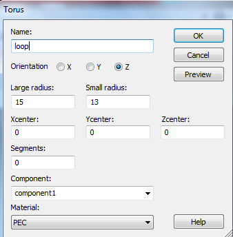
Fig. 2.1.1 Assigning radius values
In order to excite the loop antenna there must be a gap in loop for that you need to make a small brick and cut that brick at that point. The values for that gap are shown in above table and figure.

Fig. 2.2 Creating a gap in loop

Fig. 2.3 Gap created in loop
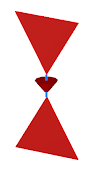
Excitation: To excite the loop antenna select pick face center option and pick the point just at the center of circular loop as shown in figure 2.4
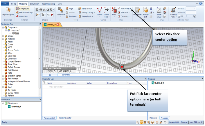
Fig. 2.4 Excitation of loop antenna
To simulate the loop antenna press simulation tool and discrete port and a pop up window will appear then you need to apply and press OK. After doing so you need to press the setup solver and set that solver with accuracy up-to -30dB. Press start to run the simulation and wait till it finishes.

Fig. 2.3 Simulation of loop antenna 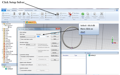

Fig. 2.4 Setting up setup solver
Step 3. Results
After simulation the check the results and determine weather antenna work well or not. From given figure it is shown that there is much loss in antenna at the return loss is higher than expected. So therefore to minimize the loss of antenna you shall optimize the loop.

Fig. 3.1 S11 of loop antenna
In order to optimize the results you need to make 2 more loop above the designed loop at certain distances. The final design can be seen in figure 3.3
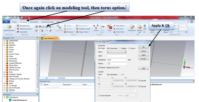
Fig. 3.2 Increasing the number of loops in antenna

Fig. 3.3 Final design of loop antenna
After simulation of final design the results has been drastically improved which can be seen from given figure below. The return loss is very minimum and desirable at the resonance frequency of 3GHz.


0 Comments