


Yagi-Uda Antenna Design
Antenna Theory: This is a type of linear wire antennas which was invented by two professors of Japan Yagi and UDA. The fashion of this antenna is in form of an array which consists of active or driven element and a few parasitic elements.
The driven element consist of folded dipole whose length is 𝜆 /2 and the parasitic elements consist of one
reflector and a few directors. Furthermore the length of reflector is greater than 𝜆/ 2 and it is located behind the active
element. The length of each director is
less than 𝜆 /2 and it is placed in front of active element. Moreover the
spacing between each element is non identical and hence it can be considered as
non-linear array. The radiation pattern of this antenna is unidirectional and gives directivity of 7dB.
Design Formulas
Length of driven element
Length of reflector

Spacing between reflector and driven element
Spacing between director and active element
or
Spacing between directors
Diameters of element
Length of Yagi UDA array
Advantages
It is easy to design.
It has small size and low weight as compared to other antennas
It is low cost antenna and easy maintenance.
Disadvantages
It is very sensitive when frequency is changed.
Require more number of elements.
Bandwidth and gain is limited.
Applications: This antenna is used for high frequency applications like TV reception and transmission
Designing of Yagi UDA Antenna in CST MWS.
Objective: To design a three element Yagi-UDA antenna at resonating frequency of 1000 MHZ.
Step 1. Parameter Calculation
Initially the lambda is calculated by using formula lamda=c/f.
where c is speed of light and f is resonating/center frequency. This gives the reflector length of antenna. The other parameters are also calculated based on formulas already discussed in this tutorial. The parameter list can be seen below.

Fig 1.1 Parameter List
Step 2. Designing
Now you have calculated the list of parameters it's time to design the antenna in CST MWS. For that you need to perform following minor steps. All of these highlighted steps are already explained in half wave dipole antenna design tutorial.
1. Create new project.
2. Select Antennas
3. Click on Wire
4. Select time domain
5. Enter frequency range
6. Final Summary
Now you have created a project. It is time to construct a cylinder of 150mm length which is aligned with z axis and it is given below. Click Modeling tab>>torus and press esc. There you shall find a pop up window asking you to input values. All of the values are mentioned in table.

Fig. 2.1.1 Reflector of 150mm length

Fig. 2.1.2 Reflector of 150mm length

Fig. 2.2 Driven element of Yagi UDA antenna
To create a director of Yagi UDA antenna of 120mm length and 0.1 radius do the same step of reflector with updated value of director element.
Note: There must be separation between driven element and director. Separation values are mentioned in above table.
Now after designing the complete antenna elements there is need to excite the antenna's driven element which lies in between reflector and director. So therefore to excite the antenna you need to put a small cut in center of driven element of length 0.5mm or 1mm.
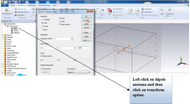
Fig. 2.3 Creation of gap in driven element
Excitation: a discrete port is used to excite the driven element of Yagi UDA antenna with impedance of 73 Ohms.

Fig. 2.4.1 Excitation of Yagi UDA antenna

Fig. 2.4.2 Excitation of Yagi UDA antenna
Step 3. Results and Analysis.
Return loss of antenna is shown below which shows that antenna resonates very well at the center frequency with minimum return loss less than -10dB.

Fig. 3.1 Return Loss of designed antenna
Step 4. Conclusion
In this tutorial the YAGI UDA antenna was completely explained and designed in CST microwave studio. All of the results of antenna were sufficient and meet the requirements.
Top 5 Frequently Asked Questions of Yagi UDA Antenna
1. What is a Yagi antenna used for?
Ans. It is used for TV reception, ham radio and as bridge antenna.
2. How does a Yagi UDA antenna work?
Ans. It works on mutual coupling between driven element and it's parasitic elements.
3. Why is Yagi UDA antenna used?
Ans. It is used for transmission and tv reception as it has higher gain and directivity.
4. How can I increase my Yagi UDA antenna?
Ans. By adding number of directors the size can be increased and in that case higher directivity is achieved.
5. How far can a Yagi antenna reach?
Ans. It can reach 10 miles of distance due to it's directional radiation pattern.


0 Comments