

Horn Antenna Design in CST MWS
Objective: To understand, design horn antenna and observe the simulated results.
Antenna-Theory: It is a type of antenna in
the shape of helix. Its polarization and radiation properties depend on the
diameter, pitch, number of turns, wavelength, excitation and spacing between
the helical loops. Helical antenna consists of helical loops made of thick
conductor which give the appearance of screw thread.

Fig. 1.1 Horn antenna
Step 1. Parameter Calculation
The center frequency of the required helical antenna is 3 GHz. However the coil radius, coil height, number of turns of coil and angle increment is shown below in table.
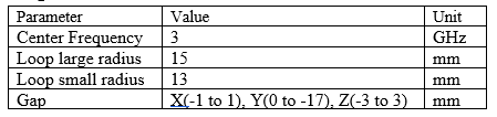
Fig. 1.2 Design values of horn antenna
Step 2. Designing
As you have list of parameters it's time to design the horn antenna in CST software. For that you need to perform following minor steps. All of these highlighted steps are already explained in half wave dipole antenna design tutorial.
1. Create new project.
2. Select Antennas.
3. Click on horn.
4. Select time domain.
5. Enter frequency range.
6. Final Summary.
After creating a CST MWS project for horn antenna. Now construct a waveguide model by selecting using brick tool. All of the values are mentioned in table.


Fig. 2.1 Constructing a waveguide model
Now construct a square shape surface of 2mm thickness called horn just away from the waveguide.

Fig. 2.2 Constructing a horn surface
Now pick the front face of waveguide and back face of horn surface and use loft option. This can be seen in image below.

Fig. 2.3 Creation of Wave guide
Now add these 3 parts together using boolean operation.
Fig. 2.4 adding the parts

Fig. 2.5 Cutting the parts for excitation

Fig. 2.6 Selecting boundary

Fig. 2.7 Waveguide port
Fig. 2.10 Simulating the antenna
Step 3. Results


0 Comments